Today class we have known how to calculate and measure the resistance of inductor and capacitor in AC circuit.
Given the peak value of V , we need to find Vrms since V avg is o in AC circuit
1.set up the equipment and circuit
2. Set logger pro. time duration 0.5 second. 240 samples per second. Graph potential vs time and current vs time. Fit equation. A =Imax, A=Vmax
3. calculate and compare experimental value and theoretical value of V rms and I rms. calculate percent error
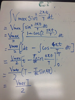
equation used: Vrms=V max/sqrt2
deduct the equation of I (t)
Draw the voltage and current vs time on whiteboard
Z is a new term impedance we used for representing "resistance" of inductor and capacitor(or total of L,R C)
This is the graph for 470 mC capacitor in AC circuit. As we can see, the peak value is always the same in sin graph, We use the same method to calculate the V rms and I rms using V max and I max
The circle is Voltage vs current graph
Then we calculate the experimental values and theoretical values of Xa which is the resistance of capacitor. We get a big error out of our expect.
Finally, we use the same procedures to repeat over the procedure we did for resistor, capacitor and draw them in logger pro and calculate the XL
Use the given condition we deduct the equation for current given inductance and voltage
Conclusion:
For ressitor we compare V rms and I rms . V max/sqrt2=Vrms, I max/sqrt2=I rms
However we compare XL and Xc in the last two experiments. Because there two ways to calculate them once given the inductance and capacitance.
Here is the equations:
For theretical, we use Xc=1/2pifC and XL=2pifL
For experimental we can use wither Vmax/I max or Vrms/I rms for both simply because their ratios are the same.


No comments:
Post a Comment