Monday, 8 June 2015

Lab25 June2 RC and LRC in AC circuit

Quick review on the most helpful LRC circuit equation. Impedance Z =sqrt(R^2 +(Xc-XL)^2) and the Irms=Vrms/Z. Assume we double the frequency, the current will be doubled.


Connect resistor capacitor series in AC circuit and measure the voltage and current, draw the graph on logger pro and find the V max and I max.Compare the experimental value with the theoretical values using impedance equation.

This is the circuit board where we connect resistor and 470 F capacitor


Next, we move add inductor into the previous circuit in series and repeat the measurement.This is the graph we get form logger pro 

After adjusting the time interval, we get a smooth sin graph. 

This is the current vs time graph.

We calculate the phase shift for the previous graph using (XL-Xc)/R

This is the data for comparing theoretical / experimental value of I and V in RC circuit

This is the data for comparing theoretical / experimental value of frequency in LRC circuit


Conclusion:
We measured V and I in LRC circuit. It is a different pattern  and we can calculate the "resistance" Z.
We review and practice the equation for impedance Z,which is similar to resistance. We find that if the LC circuit is in resosance the V0is 0 since the impedance is 0; and we have known there are phase shift that we can calculate between the V and I in LRC circuit.


lab23May26 RL circuit

Given N,Area and length,calculate the inductance of the inductor:
L=uNA^2/L=7.6hernry

Given 18 gauge copper, find the resistance using the equation=pL/A
0.001 is diameter of the 18 gauge wire
0.05 is the radius of 

Next, we calculate the time constant L/R=5*10^-6 s


Experiment:
1. Adjust the oscilloscope to square mode and function generator to 40kHz, Hit standby to see the graph. 
2. Connect 150 ohm resistor, 110 V inductor, and oscilloscope in parallel. Find the frequency of the graph.
Time div=5*10^-6 second, and we estimate the unit of time is around 0.6.So our period is 
0.6*(5*10^-6)=3.25*10^-6 s

1.


2.

Based on the graph, find the inductance and compare to the theoretical value.

Experimental value:
time constant=3.25*10^-6 s/In(2)=4.69*10^-6 
L=R*time constant=150*4.69*10^-6=730 mH


Theoretical value:L=uNA^2/L=740 mH

We are introduced to RL circuit. RL ciucuit has a inductor and resistor in parallel. As the current in the circuit increases, the current flows through inductor increases exponentially  to the maximum value
I(t)=Imax(1-e^(-t/timeconstant))
Time constant is L/R
solve a problem:
1A circuit contains a 35.0 mH inductor in series with a R1 = 120 ohm  resistor, both of which are in 
parallel with a R2 = 730 ohm  resistor and a 45.0 V battery. The switch is closed for 170 micros and 
then opened. 
 (A) What is the time constant when the switch is first closed?
(B) What is the value of the current in both resistors at the moment the switch is opened at 170 micros? 
 (C) What is the voltage drop across both resistors at 170 micros? 
(D) How long will it take for the voltage drop across the inductor to be equal to 11.0 V after the switch is closed? 
(E) What is the time constant of the circuit after the switch is open at 170 micros? 
(F) How much energy is dissipated in the two resistors after the switch is open at 170 micros?


process of solving part D:


Conclusion: The square graph shows that V and I are different if we add the inductor into the circuit since it stores energy . As we deduct earlier, we will get a steady value of I finally due to the time constant,


lab24 5-28 AC circuit

Today class we have known how to calculate and measure the resistance of inductor and capacitor in AC circuit.
Given the peak value of V , we need to find Vrms since V avg is o in AC circuit


1.set up the equipment and circuit
2. Set logger pro. time duration 0.5 second. 240 samples per second. Graph potential vs time and current vs time. Fit equation.   A =Imax, A=Vmax


3. calculate and compare experimental value and theoretical value of V rms and I rms. calculate percent error
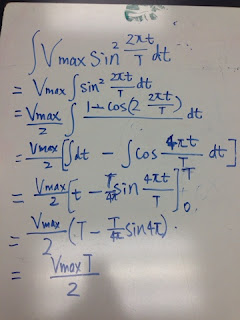
equation used: Vrms=V max/sqrt2


deduct the equation of I (t)

Draw the voltage and current vs time on whiteboard

Z is a new term impedance we used for representing "resistance" of inductor and capacitor(or total of L,R C)


This is the graph for 470 mC capacitor in AC circuit. As we can see, the peak value is always the same in sin graph, We use the same method to calculate the V rms and I rms using V max and I max
The circle is Voltage vs current graph


Then we calculate the experimental values and theoretical values of Xa which is the resistance of capacitor. We get a big error out of our expect.


Finally, we use the same procedures to repeat over the procedure we did for resistor, capacitor and draw them in logger pro and calculate the XL


Use the given condition we deduct the equation for current given inductance and voltage

Conclusion:
For ressitor we compare V rms and I rms . V max/sqrt2=Vrms, I max/sqrt2=I rms
However we compare XL and Xc in the last two experiments. Because there two ways to calculate them once given the inductance and capacitance.
Here is the equations:
For theretical, we use Xc=1/2pifC and XL=2pifL
For experimental we can use wither Vmax/I max or Vrms/I rms for both simply because their ratios are the same.


Lab22 Electromagnetic Induction

We did several questions on activPhysics about magnetic flux and induced emf.

And the answers reveal that several rules we need to know about relations between magnetic field and induced emf. For example the angle between area and magnetic field is 90 and we get 0 emf; 

Due to the fact as we invert the current direction the force will pull invert the stick
When Prof Mason turn on the generator, the metal rod pulled in 


In the next activity, we look at Motional EMF and answered the questions on the whiteboard and we see some of the useful equations like flux=BvL..


We leanred about inductor is useful in circuit and deduct the equation above.

And in comparison, we find a pair match the equation of inductor which is for capacitor. The capacitance has relations with I and V and by that saying, we can use V and dI/dT to calculate capacitance and use I and dV/dt to calculate Inductance!

We plug in the definition equation for inductor into the magnetic flux equation. What happens?
We find the realtionship between emf , current and inductance! If we know the rate of current, coil area, loop count, inductance, we can calculate the emf.

Next,we use this equation we deducted previously to solve a problem.--Inductance of solenoid


We can also deduct the unit of inductance L which is khm^2/C^2, or henry


We decrease the current, what change will be for the graph?


This is the solution we find very useful during solving the activphysics question. It is a problem in which asking current, given the ratio of time divided by time constant


This is answer to RL circuit quesitons in activPhysics. We found that when an inductor is connected, we have an induced emf that is opposite of the emf from the battery supplying the current. As time increases, the inductance increases and as resistance increases the inductance decreases.  If the inductance is large, we get that the current will reach equilibrium slower than if we increase the resistance which will allow for the current to reach equilibrium faster. The relationship is confirmed in our time constant relationship with resistance.


conclusion: We have practiced our knowledge and several useful equations of the RL circuit, inductor, magnetic field and induced emf.